In todays project I created a frame for a g clamp that is comtrolled by a spreadsheet. Changing the clamping height in the spreadsheet updates the model.
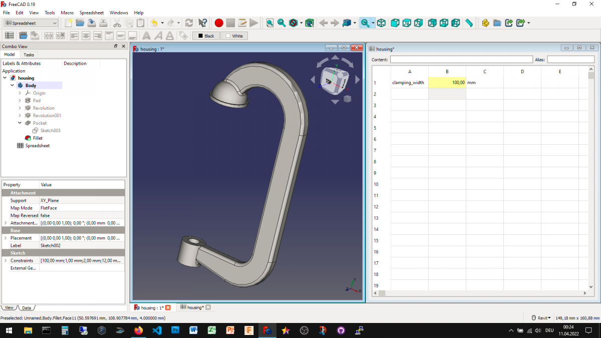
Controling the clamp frame through a spreadsheet inside FreeCAD
The initial clamping height of this clamp frame has been designed as 100 mm. The underlying sketches have been created with the clamping height as a variable parameter in mind. In order for the 3D model to be stable, changing the clamping height should not change the number of topology elements. When that is the case, the clamping height can be changed to nearly any value.
In order to control the clamping height of this frame from a spreadsheet I first created a new spreadsheet. In the first row of the spreadsheet I modified 3 cells: A1: “clamping height”; A2: setting alias to clamping height and an initial value of 100; A3: mm (the unit of the clamping height value)
Now I set all the neccessary dimensions to reference cell A2 with the alias clamping height. Finally all connections between the 3D model and the spreadsheet have been made. I am now able to modify the clamping height of the 3D model by changing the valu ein the spreadsheet.
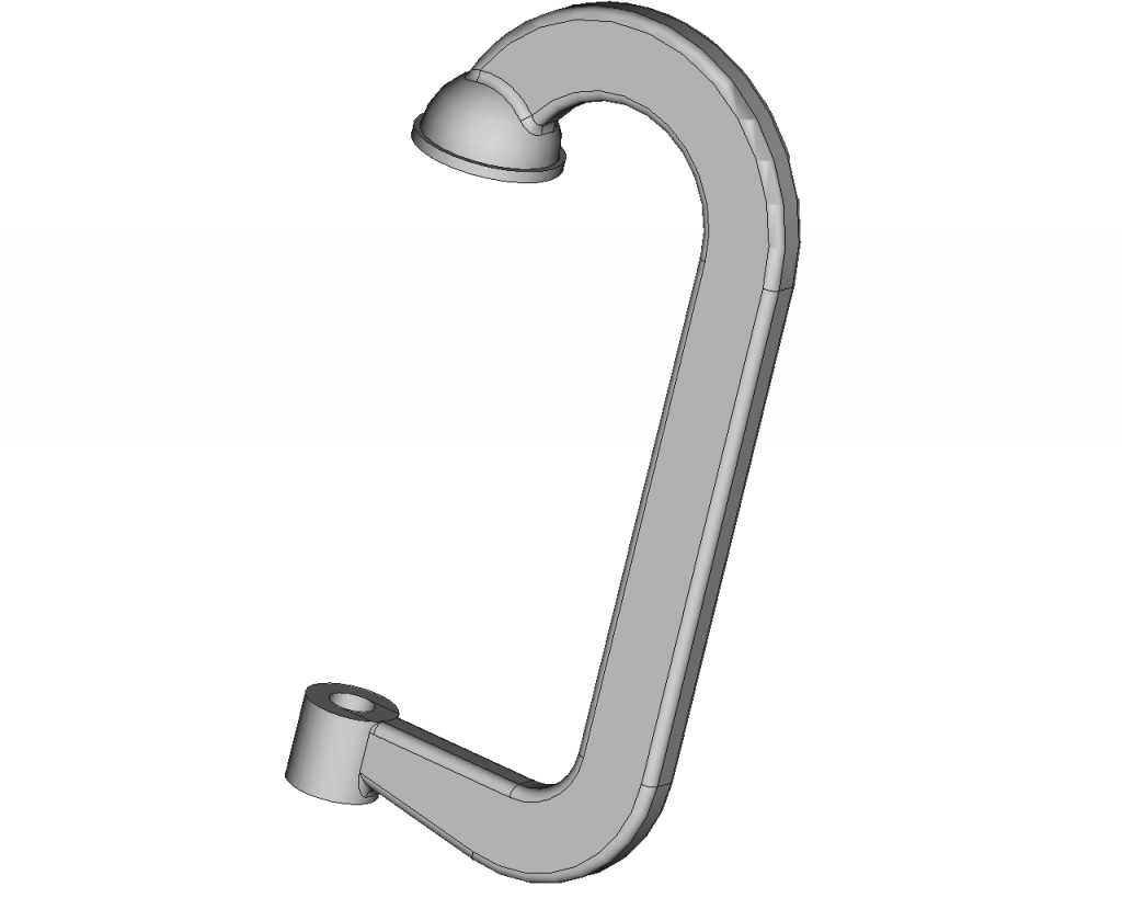
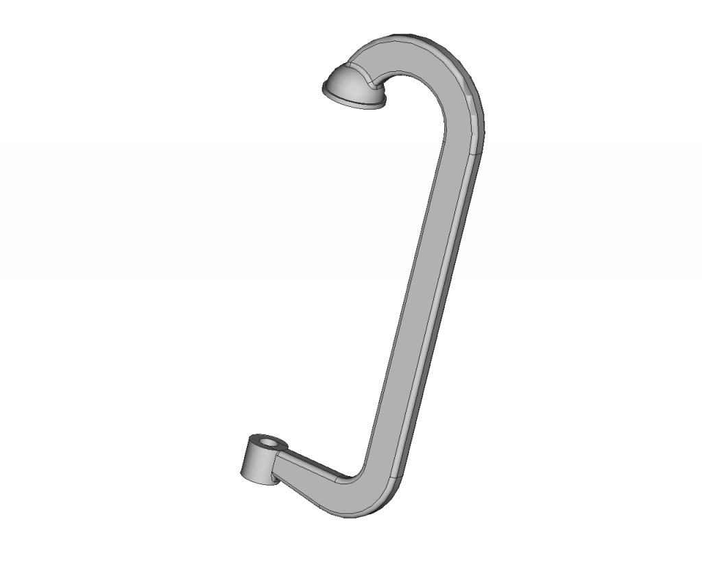
I created three different variations of the clamp frame with a clamping height of 100 mm, 150 mm and 300 mm.

Tomorrow I will combine this frame with a screw and make a spreadsheet driven assembly out of it.
Getting Started with FreeCAD
Jumpstart your first 3D CAD project with the open-source software FreeCAD and this illustrated step-by-step guide.

Exploring newest story
- Learning from scratch how to create custom features in FreeCADThis will give you an overview on how to get started with developing custom FreeCAD features. To get started follow the Create a FeaturePython object part I tutorial on the FreeCAD wiki. The examples in this blogpost are from the tutorial in the FreeCAD wiki. Setting up the folder structure for the custom feature project… Read more: Learning from scratch how to create custom features in FreeCAD