Designing a functional shaft on paper
In order to demonstrate the application of the newly created surface roughness and edge annotation symbols, I created this real-life project of a functional shaft used in a transmission machine.
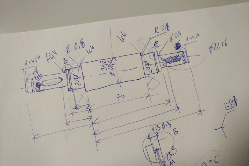
As the first step I created a hand drawn sketch of hte shaft to define all the requirements. The requirements consist of dimensions, fits, surface roughness and edge break annotations. All the requirements are based on current best practises and norms in mechanical engineering.
Its always better to quickly sketch out the part you are designing on paper, so that when you model it in FreeCAD you dont have to think about that.
Modeling the shaft in FreeCAD Part Design
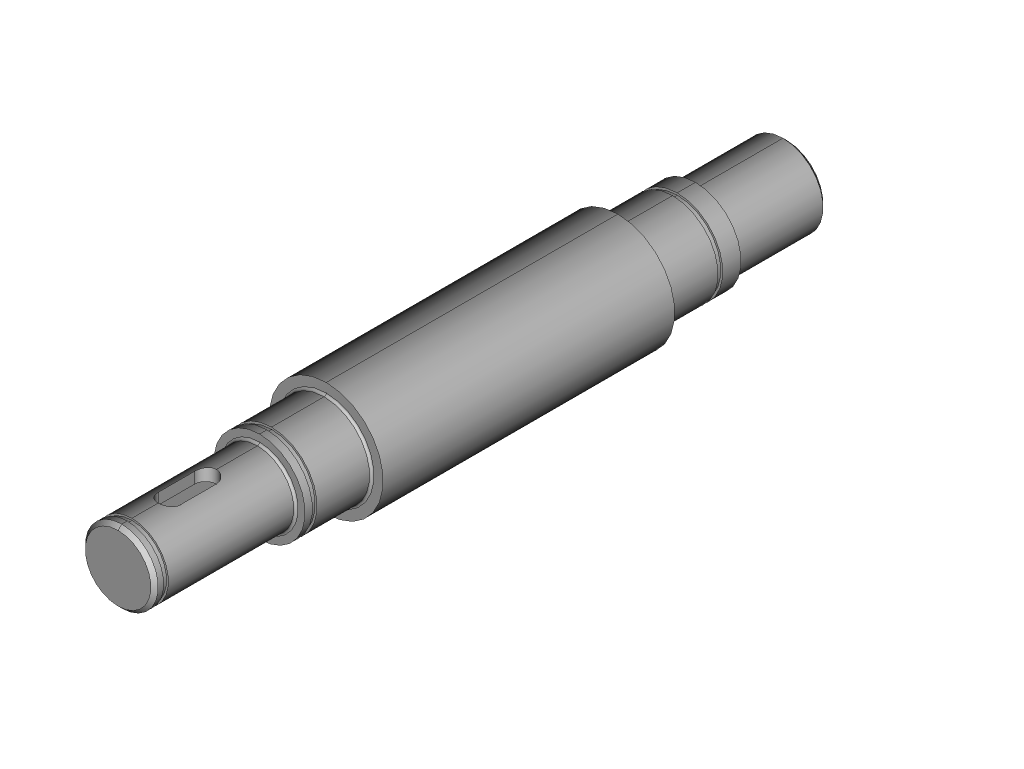
After I had finished creating the hand drawn sketch on paper and established all the dimensions and other requirements, I modeled the shaft in FreeCAD Part Design.
Modeling shafts in FreeCAD is usually very easy. You first sketch half of the cross-section and revolve that. Afterwards you add keyways and other features.
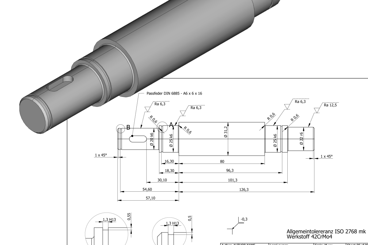
Deriving a technical drawing for manufacturing in TechDraw
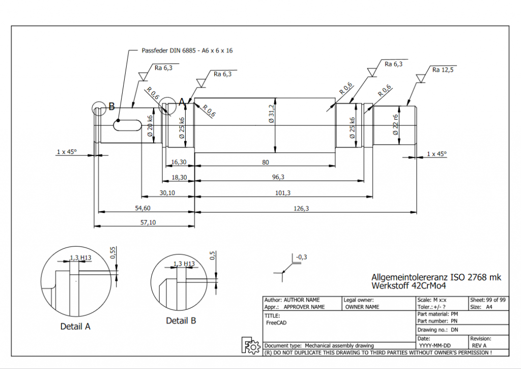
Now that the 3D CAD model has been created I was able to derive a view projection of the 3D CAD model onto a drawing page. Creating the manufacturing drawing was the whole purpose of this exercise. I wanted to make use of the surface roughness and edge break annotation symbols that I created earlier this week. The reason I wanted to try them out is to see if they are usable in a productive environment and process. To create the full technical drawing in TechDraw I did the following:
- Place projection view on the page
- Create detail views of the locking ring grooves
- Add all nominal dimensions.
- Shorten the number of significant digits to a more senseful setting
- Add diameter symbols to diameter dimensions and tolerances
- Add our new surface roughness symbols with a modified balloon annotation
- Add general edge break annotation symbol
You can learn how to apply those surface roughness and edge break annotation symbols to your TechDraw manufacturing drawing in a previous blog post Creating Surface Roughness Annotations.
Getting Started with FreeCAD
Jumpstart your first 3D CAD project with the open-source software FreeCAD and this illustrated step-by-step guide.

Exploring newest story
- Learning from scratch how to create custom features in FreeCADThis will give you an overview on how to get started with developing custom FreeCAD features. To get started follow the Create a FeaturePython object part I tutorial on the FreeCAD wiki. The examples in this blogpost are from the tutorial in the FreeCAD wiki. Setting up the folder structure for the custom feature project… Read more: Learning from scratch how to create custom features in FreeCAD