Defining the parameters of the t-slotted machine table in a spreadsheet Modeling the t-slotted table in Part Design and connecting to spreadsheet Creating multiple variations of the t-slotted machine table by changing the spreadsheet parameters
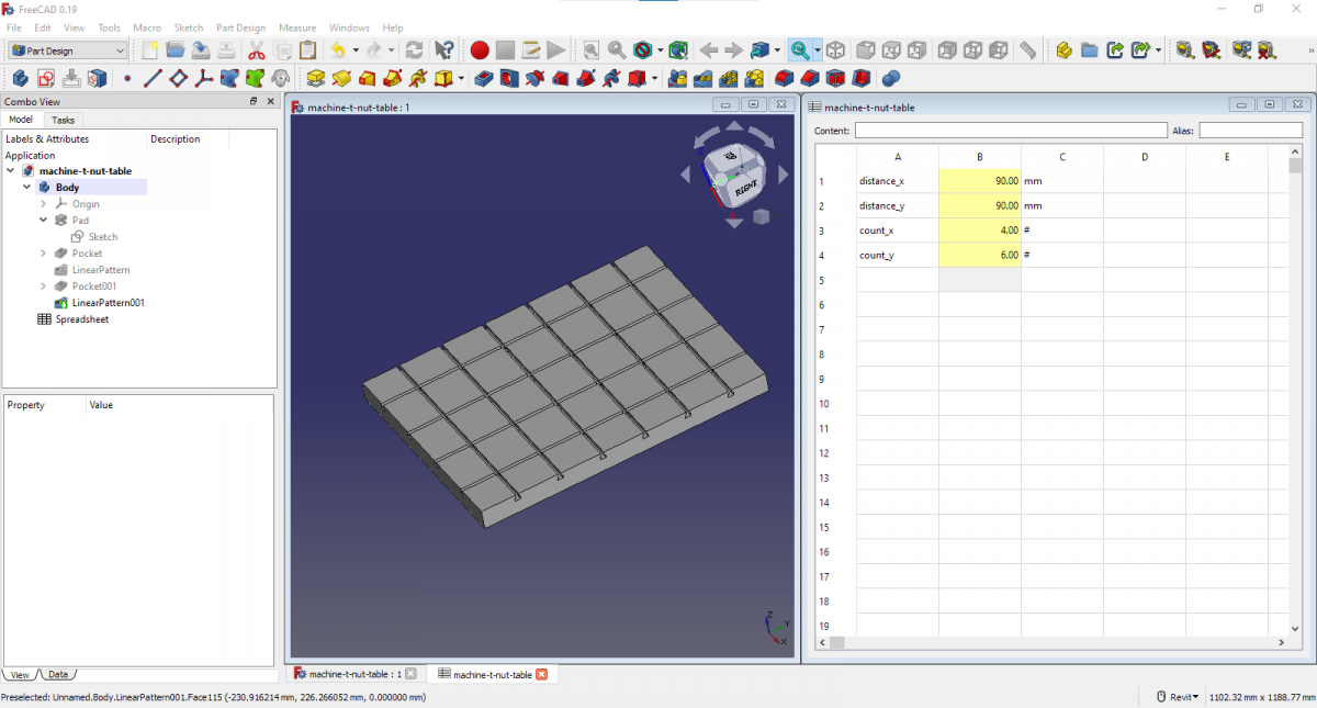
Defining the parameters of the t-slotted machine table in a spreadsheet Modeling the t-slotted table in Part Design and connecting to spreadsheet Creating multiple variations of the t-slotted machine table by changing the spreadsheet parameters
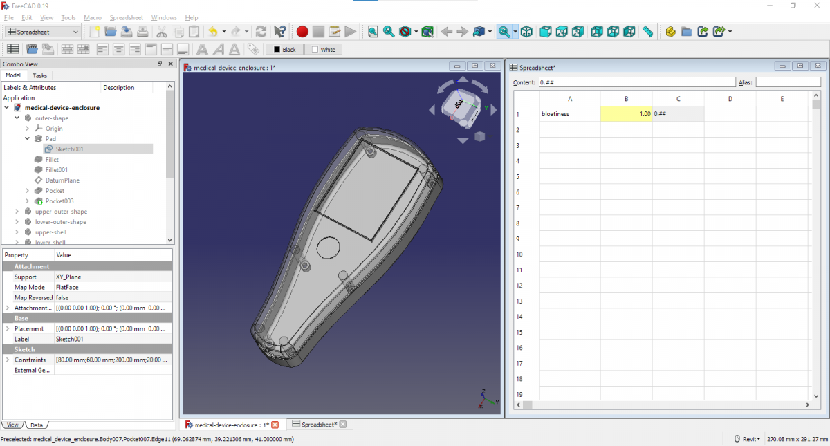
Creating the medical device enclosure outline with splines Adding a descriptive parameter with an alias to a spreadsheet Connecting the geometry to the parameter from the spreadsheet Experimenting with variants of the medical device design using the spreadsheet parameter
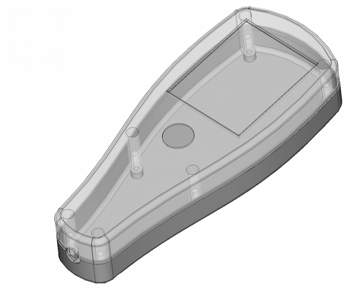
Sketching a concept of the medical device in Krita Creating the overall shape of the enclosure as a Part Design Body Shelling the solid overall shape to house the electronics Modeling internal structure of the medical device Create mating flange to align enclosure halves Cutting out openings for the mouning screws and the cable attachement
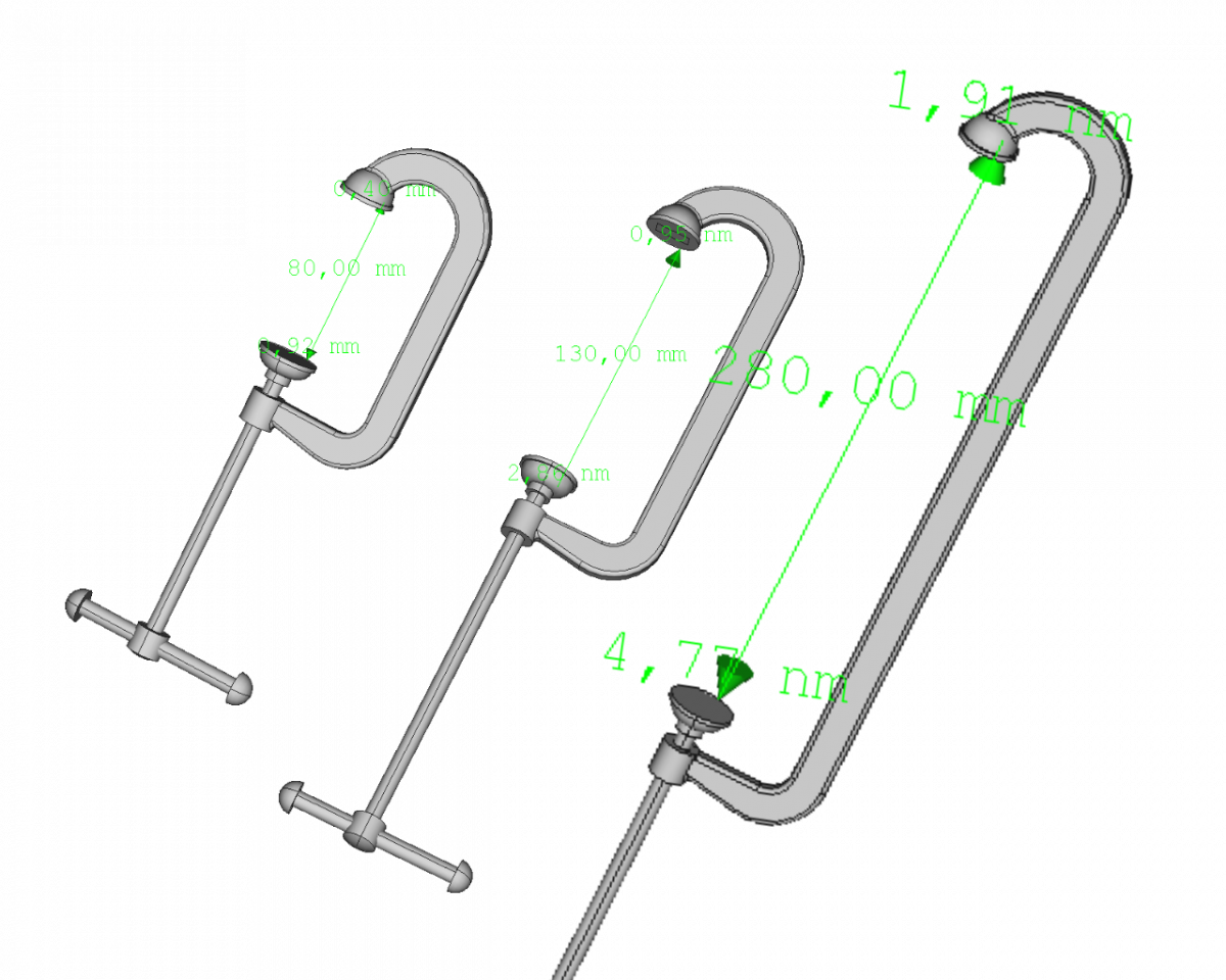
Defining a specification of the g-clamp assembly In our example of a g-clamp we are defining one specifying parameter for the whole assemly. The main driving parameter is the clamping width of the clamp. Driving parameters: clamping width All other dimensions are going to be based on that or directly reference it. Modeling all components […]
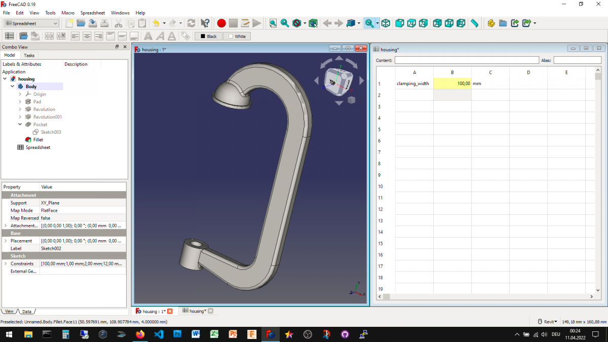
In todays project I created a frame for a g clamp that is comtrolled by a spreadsheet. Changing the clamping height in the spreadsheet updates the model. Controling the clamp frame through a spreadsheet inside FreeCAD The initial clamping height of this clamp frame has been designed as 100 mm. The underlying sketches have been […]
Yesterday I created a simple and repeatable workflow for designing electronics enclosured with two halves in FreeCAD Part Design and posted it in this blog. The blogpost consisted of step by step instructions as illustrations but had no accompanying description. Today I updated the blog post and added descriptions to every step of the workflow. […]
You will learn in this blogpost how to create simple plastic electronics housings using a repeatable workflow in FreeCAD in a illustrated way. You will need to know how to work with the Part Design workbench to understand this workflow. We will especially be using booleans Modeling the outer shape of the housing as one […]
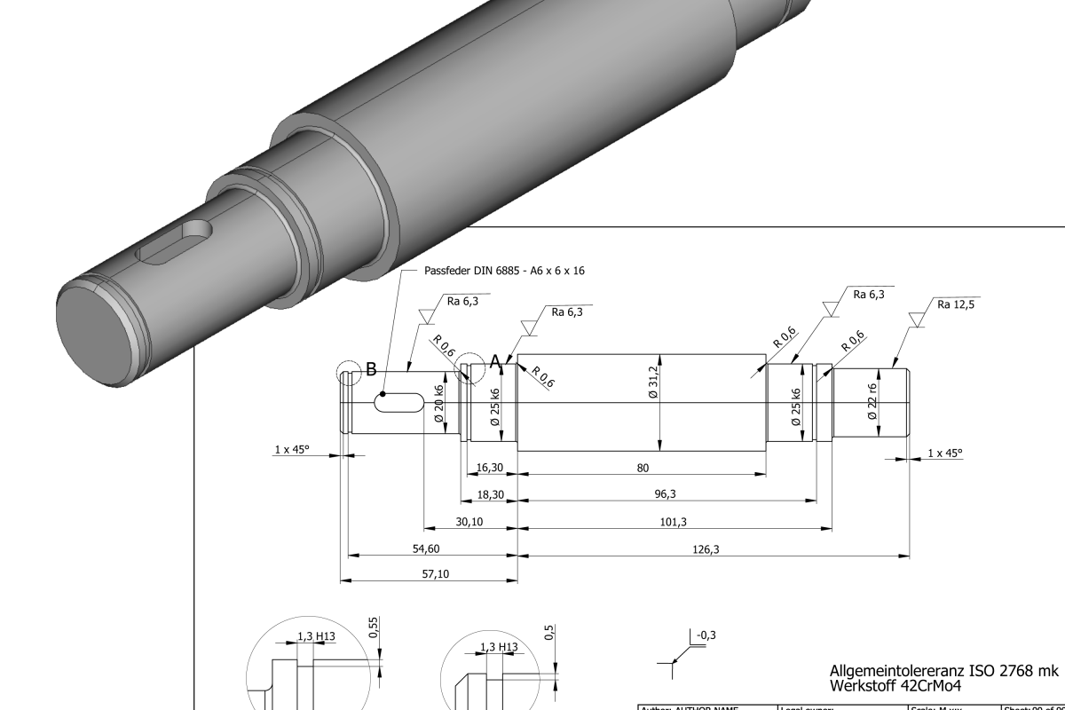
Designing a functional shaft on paper In order to demonstrate the application of the newly created surface roughness and edge annotation symbols, I created this real-life project of a functional shaft used in a transmission machine. As the first step I created a hand drawn sketch of hte shaft to define all the requirements. The […]