You will learn in this blogpost how to create simple plastic electronics housings using a repeatable workflow in FreeCAD in a illustrated way. You will need to know how to work with the Part Design workbench to understand this workflow. We will especially be using booleans
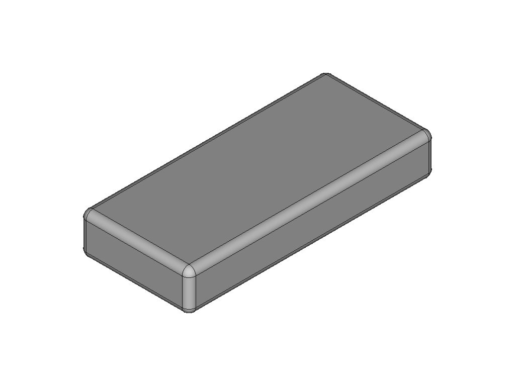
Modeling the outer shape of the housing as one body
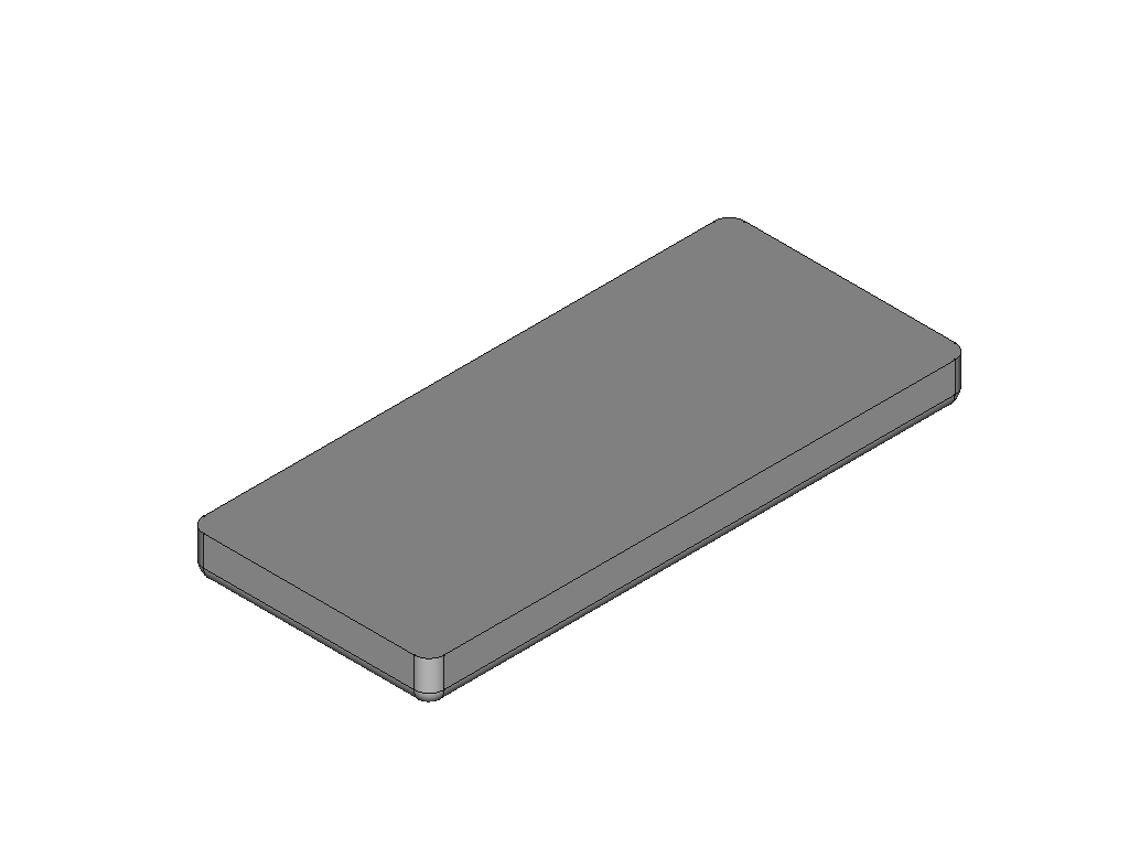
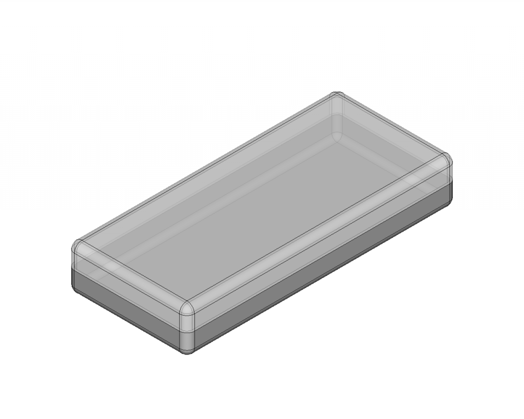
At first create a new body with the overall shape of the enclosure. In this case we create the following box with rounded corners. Maybe you can already see the resemblance of the final electronics enclosure shown above.
Spliting the outer housing shape into two halves
We want our enclosure to be made up of two halves. This way we can put anything in it. For that purpose we are going to split the initial body into two separate ones. To do this first create two clones from the overall shape. Clones are linked copies of an object. You should now have three similar shapes.
We need to remove half of each clone to create the top and bottom case of the enclosure. To remove half of a bodies shape, first create a datum plane where you want the cut line of the enclosure to be.
After placing the datum plane create a sketch that encompasses the outer perimiter of the enclosure and create a pocket in the opposite direction of what part you want to keep. The result is one half of the split enclosure.
Now activate the other clone body and repeat the same. This time doing the pocket in the opposite direction. Its important to place the datum plane for the pocket sketch in the same place that you placed the datum plane for the other half.
Both halves are still not hollow. We wouldnt be able to place anything inside those halves.
Creating a stiffening shape
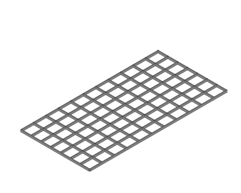
To stiffen up our enclosure we will create a stiffening mesh. Because it would be very difficult to manually follow the curves of our halves to make the stiffener fit perfectly inside our enclosure, we will use a comman boolean.
Combining the stiffening shape with the upper and lower halves with common boolean
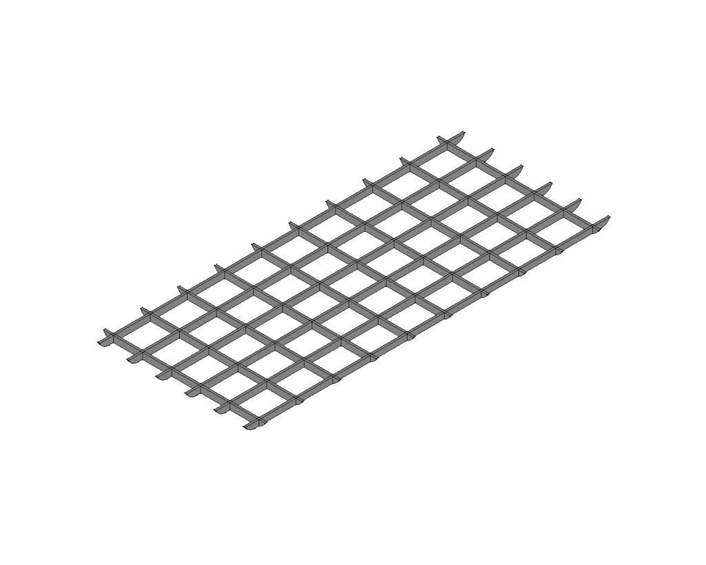
To modify the stiffener mesh so it exactly fits to the contours of the enclosure we will use a common boolean. The common boolean will create a new body with the shape that is common between the two shapes.

Using the common boolean with the stiffener mesh and the bottom half of the enclosure will produce the following example.
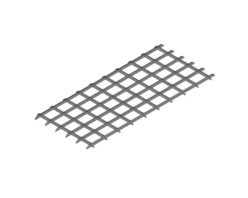
We will now also do the same with the upper enclosure half, using the common boolean. The boolean results in the following shape inside a new body.
Hollowing out the outer shape of the enclosure with Thickness
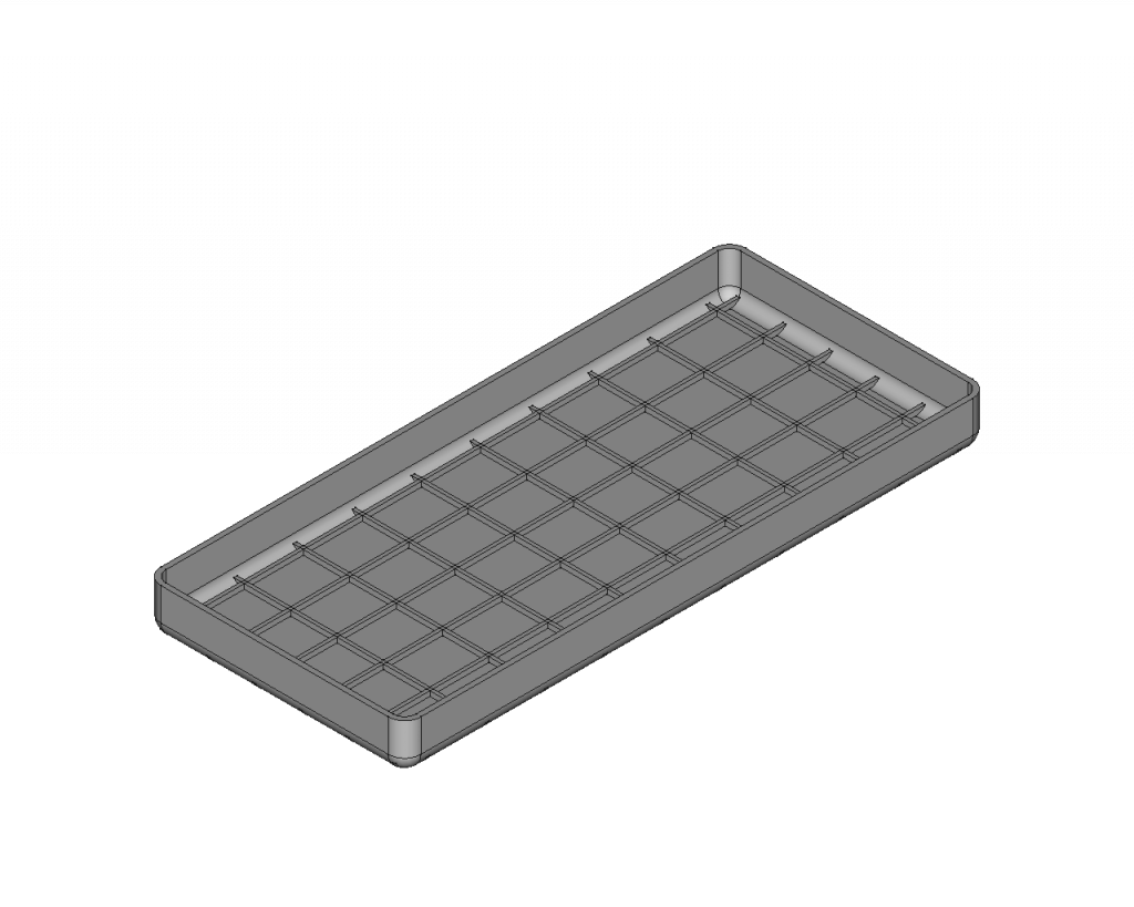
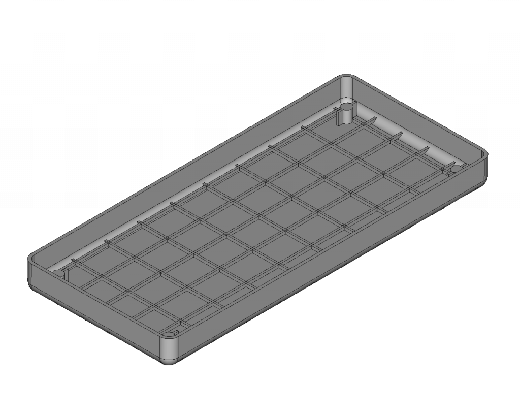
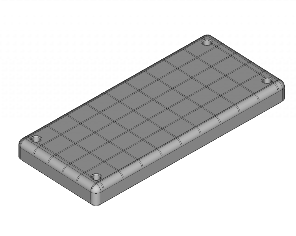
We can now hollow out the enclosure to create space for everything that is going to be contained in it. Up until now both halves are solid or “full”. Using the Thickness function will create a shell out of our full shapes. When using Thickness we select the mating surfaces to get the following result.
Combining the enclosure shell with the stiffeners using a Fuse Boolean in Part Design
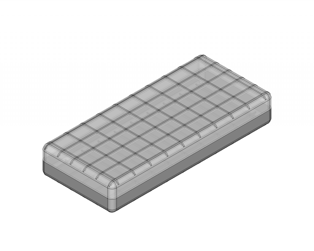
We will now combine the stiffener meshes that we cut to the contour of the enclosure with both enclosure halves. We can do this using a fuse boolean. We first fuse the upper stiffener mesh with the upper enclosure half, then we do this to the bottom one. The result already looks like a professional enclosure, but we still need some functional elements.
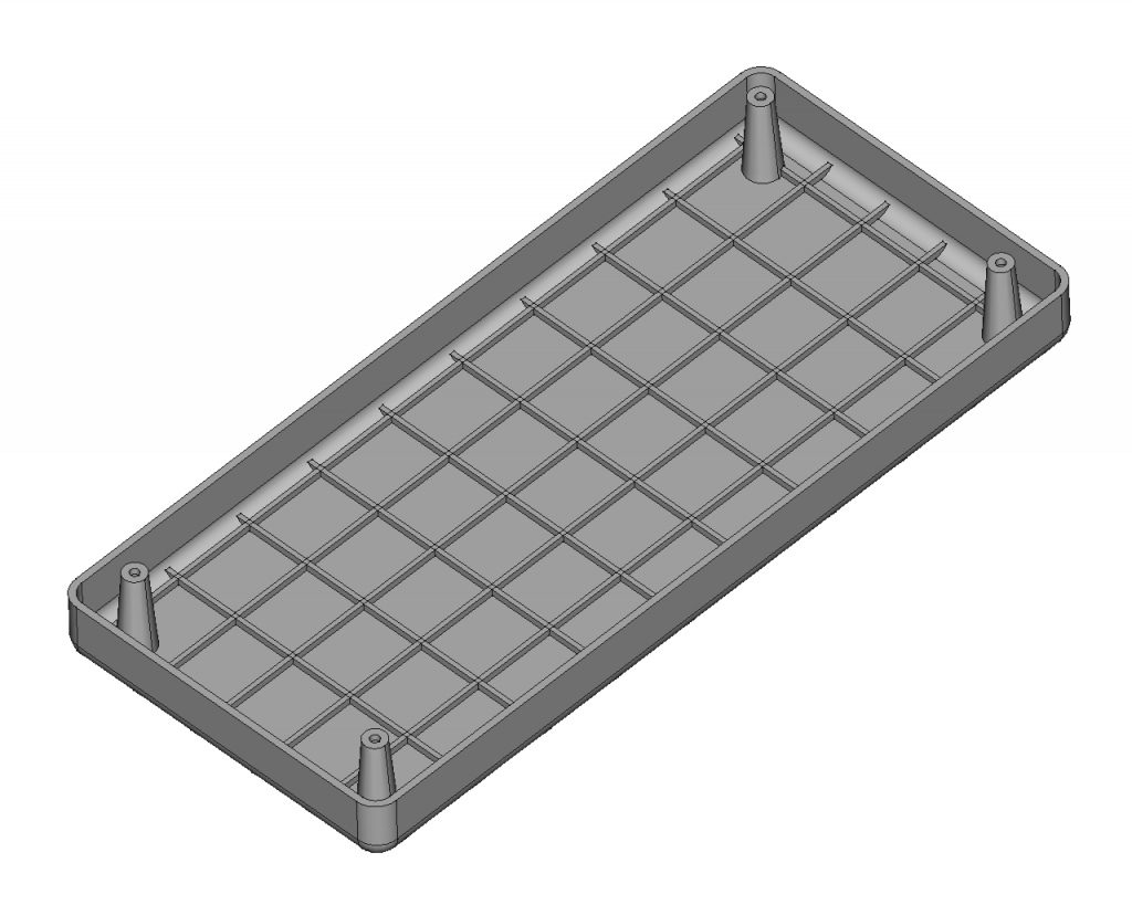
Adding embossed stand offs to the enclosure halves
To assembly our enclosure we need to have screwholes in both halves.
We first create embossed standoffs in each corner of the enclosure. This can be easily done by sketching the cross-section of one standoff in one corner, then padding it and at last creating a rectangular array by nesting a linear array inside another one. We can nest an array inside another one with the Multitransform feature.
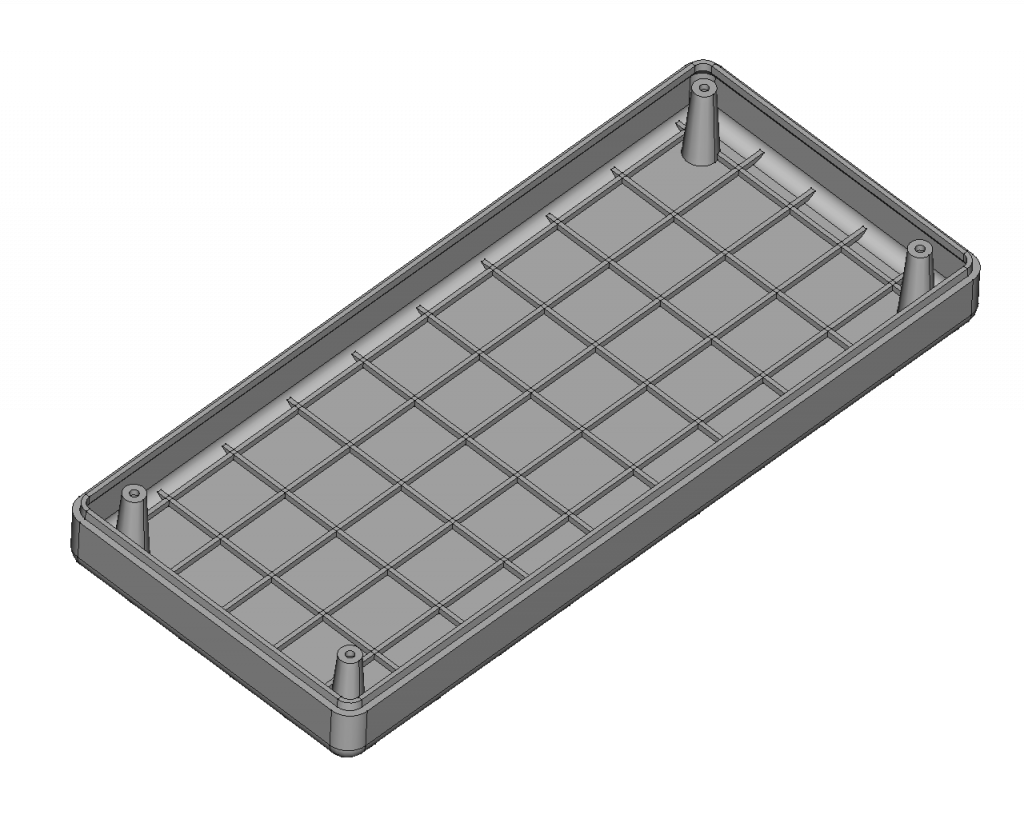
Creating holes in the embossed stand offs
The standoffs we created in the previous step cannot be used for a screw right now. We need to create holes in each of them. This is simply done by creating a hole in one of the standoffs and then doing the rectangular array using multitransform feature again. The holes are not going through the shell of the enclosure but rather have a hole just deep enough for the threadded inserts. This is going to be the front of the device.

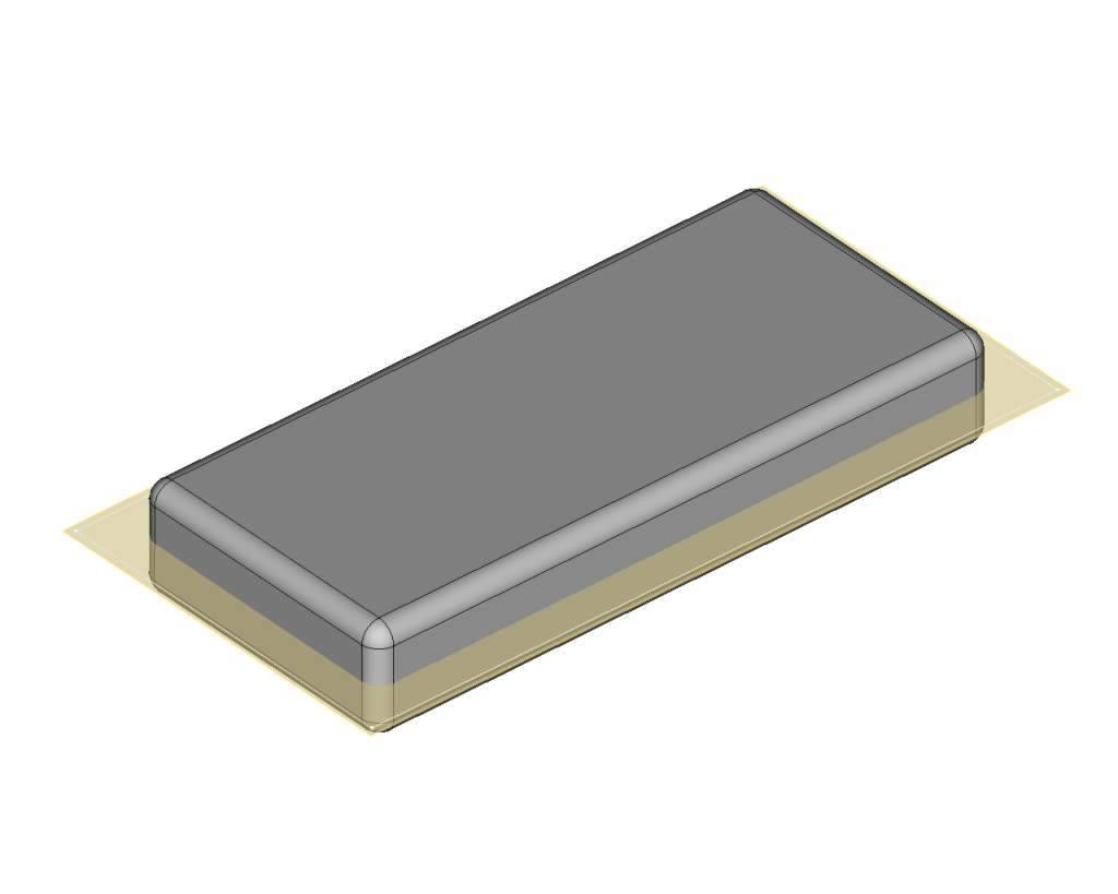
We also do the same for the other half of the enclosure. The other half is the back of the device. CMake sure your standoffs do not colide with each other when the enclosure is assembled. Its helpful to turn up the transparency to look inside the enclosure when its assembled.
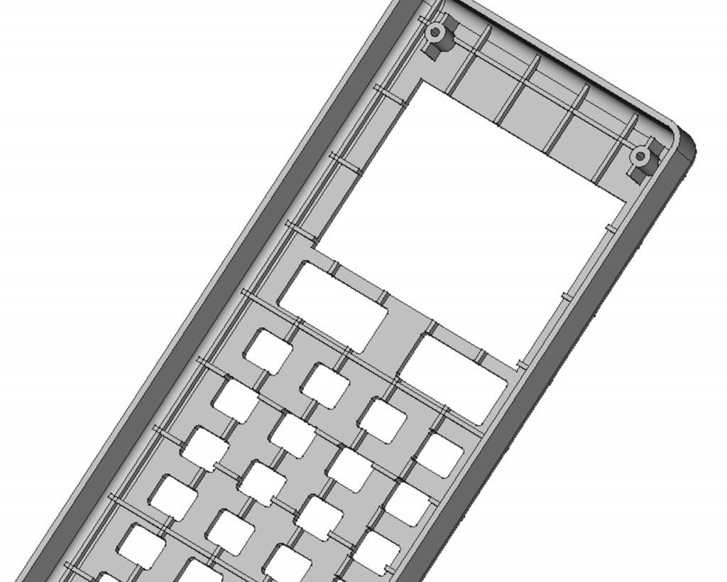
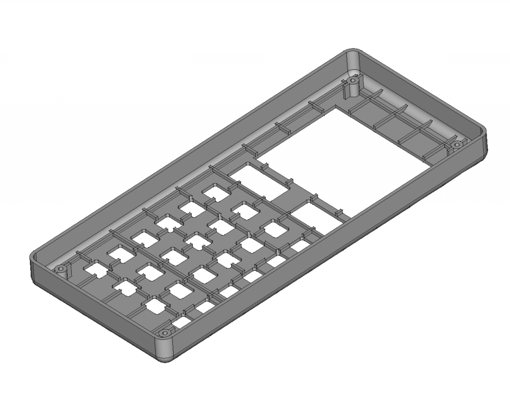
Creating cutouts in the enclosure for user input and output devices
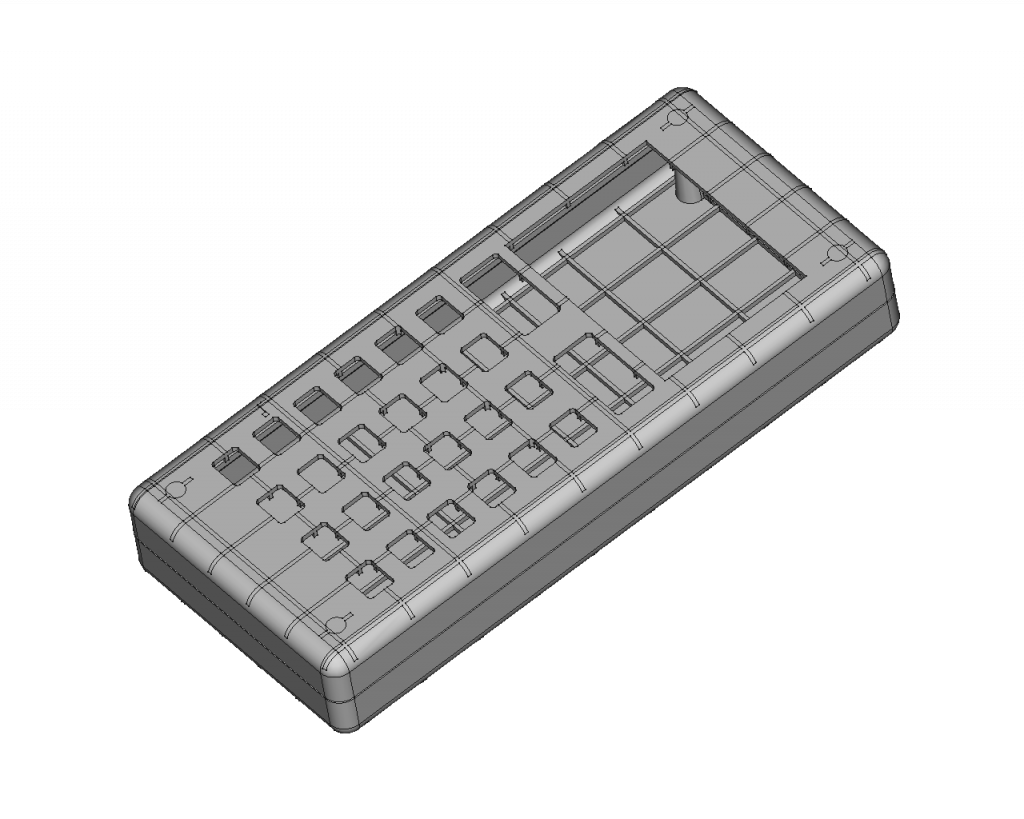
In order for our enclosure to be useful we need cutouts for the display and the keypad. To create those cutouts we will create sketches on the bottom plane of the front enclosure half and pocket them.
Adding a lip to the outer edge of the halves for alignment
We have nearly finished our enclosure. We will add a lip to the outer edge of the back half of the enclosure. We need to do this to align both halves to each other. Otherwise, both halves would slide around on the mating surface.
Radiusing all necessarry edges
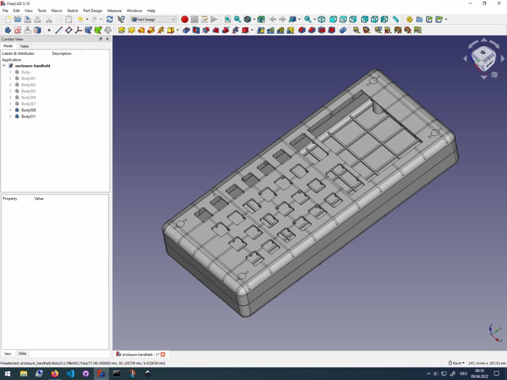
The last step of our workflow is to radius all edges. Edge radiuses should be usually done as the last step in a modeling workflow. In our example we radius the through holes for the mounting screws of the back half of the enclosure.
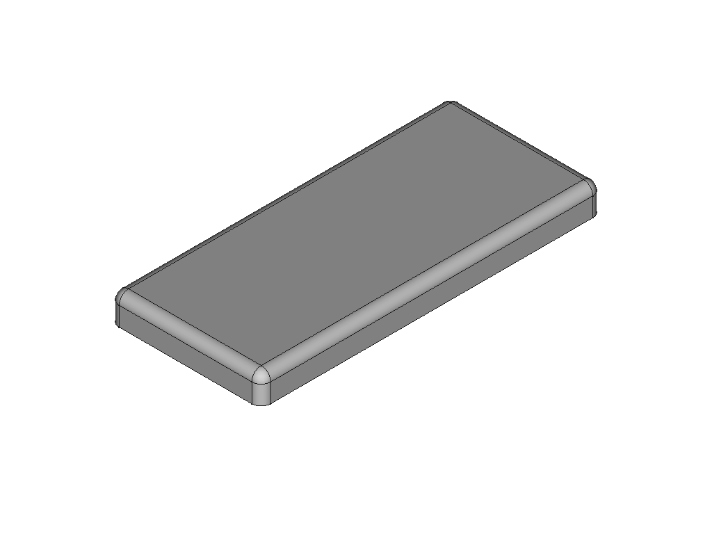
Completing the electronics enclosure
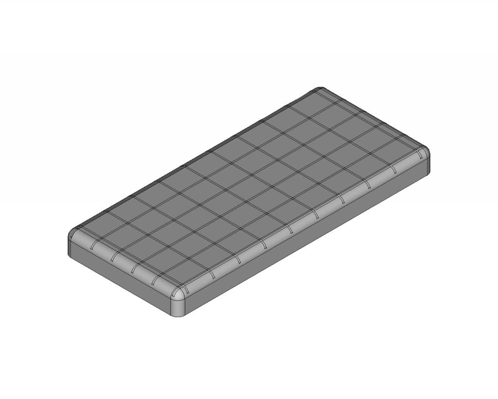
We have finished modeling our enclosure. Because we have modelled everying in place, we do not need to assemble it to see the final result.
Getting Started with FreeCAD
Jumpstart your first 3D CAD project with the open-source software FreeCAD and this illustrated step-by-step guide.
Exploring newest story
- Learning from scratch how to create custom features in FreeCADThis will give you an overview on how to get started with developing custom FreeCAD features. To get started follow the Create a FeaturePython object part I tutorial on the FreeCAD wiki. The examples in this blogpost are from the tutorial in the FreeCAD wiki. Setting up the folder structure for the custom feature project… Read more: Learning from scratch how to create custom features in FreeCAD
One reply on “Designing simple plastic electronics enclosure using a repeatable workflow in FreeCAD”
[…] Designing simple plastic electronics enclosure using a repeatable workflow in FreeCAD […]